 So
I went for a skeg very similar to the one I already use
So
I went for a skeg very similar to the one I already use
 which
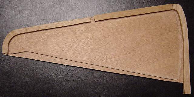
is fitted to my North Shore Mistral boat, operated by a slider control next
to the cockpit, and dropping down as a triangular shape near the stern.
which
is fitted to my North Shore Mistral boat, operated by a slider control next
to the cockpit, and dropping down as a triangular shape near the stern.
My first wooden kayak, Geyrfugl, has shown a definite tendency to be blown off course when paddled by its intended paddler, who is very light, leading to a lot of windage and not much boat in the water. She is fine with a heavier paddler (and would probably be OK with a lot of cargo, too). My second boat was also being built as a low volume kayak, and whilst I intended to paddle her, it also seemed likely that smaller members of the family would get to use her at sometime. Since almost all of the typical "British sea kayak" designs come with a skeg, and I had a lot of (positive) experience using one, I decided to build a skeg for my Hybrid Cormorant. In fact, during her maiden paddle, before the skeg was fitted in its slot, the boat proved to be very strongly tracking, and I began to wonder if I had wasted a lot of time and effort on this part of the construction. However, using the boat in bigger waves and windy conditions, and especially when paddling downwind or surfing, has shown the skeg to be a valuable addition.
There are a number of possible skeg configurations out there, such as the one sold by Chesapeake Light Craft for their kits. British boats tend to have either the NDK style of skeg (which is pulled up by a string and cleat arrangement opposing a bungie-cord which tries to deploy the skeg) or the type fitted by Valley Canoe Products, North Shore and others, which is controlled by a stainless steel cable running in a small diameter nylon tube. I've never liked the NDK style, and the CLC style involves a big deck penetration which I don't like, as much of the work must be done after the deck is attached to the hull.
So
I went for a skeg very similar to the one I already use
which
is fitted to my North Shore Mistral boat, operated by a slider control next
to the cockpit, and dropping down as a triangular shape near the stern.
 The skeg box was made from two pieces of 4mm plywood (glassed both sides
with 4 oz glass), spaced apart by 6mm ply strips. The skeg blade was also
4mm ply, again glassed both sides. The thickened epoxy used to assemble
the box added a little extra spacing, so that the skeg blade has maybe half
a millimetre clearance each side within the skeg box. This is a lot less
than the clearance seen in commercial skeg designs, and I hoped that my
careful assembly would ensure that this was not a problem. Keeping the
clearance low would mean that there was little space for water to circulate
when the skeg was up, which would avoid creating a lot of turbulence and
drag.
The skeg box was made from two pieces of 4mm plywood (glassed both sides
with 4 oz glass), spaced apart by 6mm ply strips. The skeg blade was also
4mm ply, again glassed both sides. The thickened epoxy used to assemble
the box added a little extra spacing, so that the skeg blade has maybe half
a millimetre clearance each side within the skeg box. This is a lot less
than the clearance seen in commercial skeg designs, and I hoped that my
careful assembly would ensure that this was not a problem. Keeping the
clearance low would mean that there was little space for water to circulate
when the skeg was up, which would avoid creating a lot of turbulence and
drag.
 The
pivot would be a piece of stainless steel bar cut off from a chunk I found
lying around - this is quite a large (12 mm) diameter so that the radius of
the cutout in the skeg blade should not produce too much stress
concentration as would be expected with a small diameter pivot. The bar was
cut 14 mm long, so that it would
The
pivot would be a piece of stainless steel bar cut off from a chunk I found
lying around - this is quite a large (12 mm) diameter so that the radius of
the cutout in the skeg blade should not produce too much stress
concentration as would be expected with a small diameter pivot. The bar was
cut 14 mm long, so that it would![]() penetrate both skeg box walls, but be covered by glass and epoxy at the
sides. If I was doing this again, I might be tempted to cover the ends
of the pivot with a small piece of ply epoxied onto the box.
penetrate both skeg box walls, but be covered by glass and epoxy at the
sides. If I was doing this again, I might be tempted to cover the ends
of the pivot with a small piece of ply epoxied onto the box.
![]()
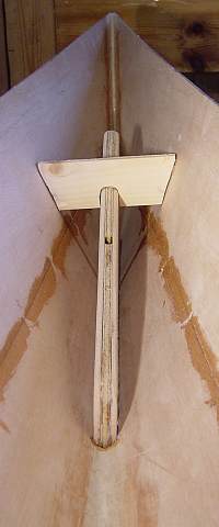 The slot for the skeg box was cut in the keel of the hull after the
inside was glassed and the box itself had been assembled. This was quite
scary since the cuts must be made at a steep angle to the surface of the
hull, keeping the saw blade vertical. I cut the slot undersized and then
sanded it out to size using coarse grit paper wrapped round a small piece
of wood. This produced a very thin edge, prone to splintering, but as this
would later be covered by glass and epoxy (and inevitably some fairing
compound), this was not a problem. The box was fitted with a few blobs
of hot melt glue, and held in the centre of the boat by a temporary brace.
The slot for the skeg box was cut in the keel of the hull after the
inside was glassed and the box itself had been assembled. This was quite
scary since the cuts must be made at a steep angle to the surface of the
hull, keeping the saw blade vertical. I cut the slot undersized and then
sanded it out to size using coarse grit paper wrapped round a small piece
of wood. This produced a very thin edge, prone to splintering, but as this
would later be covered by glass and epoxy (and inevitably some fairing
compound), this was not a problem. The box was fitted with a few blobs
of hot melt glue, and held in the centre of the boat by a temporary brace.
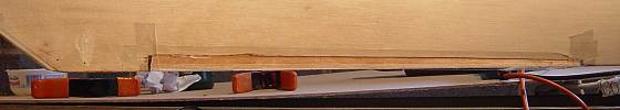 With
the skeg box temporarily fixed in position, I taped over the outside to stop
epoxy running down, then poured a runny mix of epoxy and micro-balloons into
With
the skeg box temporarily fixed in position, I taped over the outside to stop
epoxy running down, then poured a runny mix of epoxy and micro-balloons into
 the groove either side of the box inside the hull. This epoxy mix flowed
nicely into the sides of the box and formed a good fillet in the tight
V-shapes each side. This is essentially the same sort of epoxy mix I'd use
in an end-pour.
the groove either side of the box inside the hull. This epoxy mix flowed
nicely into the sides of the box and formed a good fillet in the tight
V-shapes each side. This is essentially the same sort of epoxy mix I'd use
in an end-pour.
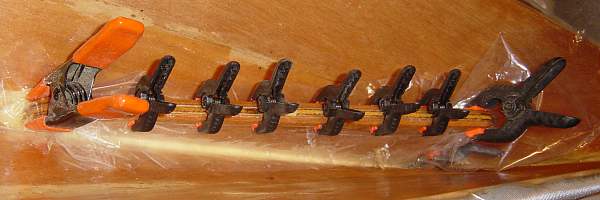 The top edge of the skeg box had been epoxy sealed, but now needed a layer of
glass to protect it. This was easier to do after the box was in place, and
was achieved by wetting out a piece of one inch tape, covering it in a
plastic film and clamping it so that the tape wrapped down the sides of the
box (the poor man's vacuum bagging approach:). The edges of the skeg box
which stood proud at the keel were then sanded fair with the hull, and any
gaps where the runny epoxy mix had not filled from inside the hull were
filled with a thicker fairing mix. When the outside of the hull was glassed,
the open skeg slot was simply glassed right over with both layers of glass
(and was not actually cut open again until after the first launch)
The top edge of the skeg box had been epoxy sealed, but now needed a layer of
glass to protect it. This was easier to do after the box was in place, and
was achieved by wetting out a piece of one inch tape, covering it in a
plastic film and clamping it so that the tape wrapped down the sides of the
box (the poor man's vacuum bagging approach:). The edges of the skeg box
which stood proud at the keel were then sanded fair with the hull, and any
gaps where the runny epoxy mix had not filled from inside the hull were
filled with a thicker fairing mix. When the outside of the hull was glassed,
the open skeg slot was simply glassed right over with both layers of glass
(and was not actually cut open again until after the first launch)
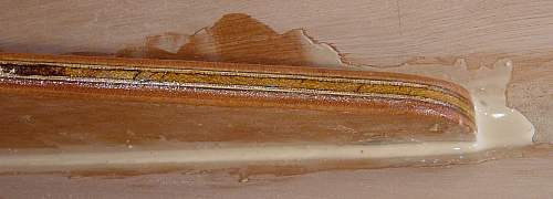
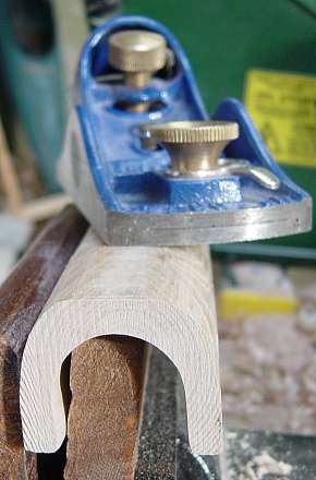 With the skeg box fitted, work could now shift to completing the hull
glassing and building the deck, which, being stripped, was a much longer
process than building the hull. In parallel with the deck stripping, I made
the components for the sliding hand control. First, I cut a square piece of
sycamore from a straight branch fallen from one of our own trees. I then
routed a deep groove into the centre of this, and sanded the bottom out by
using sand paper wrapped round a piece of dowel. Then with this piece in the
vice, I used a block plane to take down the corners to produce a piece of
With the skeg box fitted, work could now shift to completing the hull
glassing and building the deck, which, being stripped, was a much longer
process than building the hull. In parallel with the deck stripping, I made
the components for the sliding hand control. First, I cut a square piece of
sycamore from a straight branch fallen from one of our own trees. I then
routed a deep groove into the centre of this, and sanded the bottom out by
using sand paper wrapped round a piece of dowel. Then with this piece in the
vice, I used a block plane to take down the corners to produce a piece of
 channel with a side thickness slightly more than that of the deck strips. I
sealed both surfaces with epoxy, but decided that glassing the inside was
going to be too difficult. This was an error - the epoxy sealing was not
sufficient and I now have to remember to varnish the inside of this channel
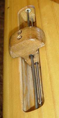
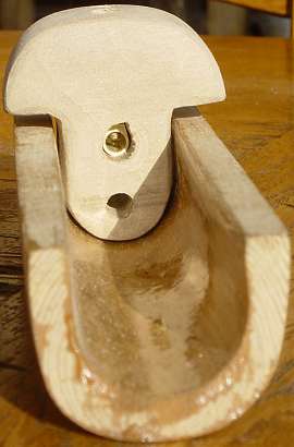
rather frequently on the finished boat. The actual slider was cut from a
piece of walnut (which didn't turn out as dark as I had hoped). There are two
holes drilled in this along the axis of the control. One is to fit on a thin
stainless steel rod to keep the slider in place, the other contains a brass
cable clamp which locks onto the control cable via two small screws which are
accessed by two more small holes drilled in the top of the slider. The brass
cable clamp was out of my scrap box - from an old broken electrical fitting.
channel with a side thickness slightly more than that of the deck strips. I
sealed both surfaces with epoxy, but decided that glassing the inside was
going to be too difficult. This was an error - the epoxy sealing was not
sufficient and I now have to remember to varnish the inside of this channel
rather frequently on the finished boat. The actual slider was cut from a
piece of walnut (which didn't turn out as dark as I had hoped). There are two
holes drilled in this along the axis of the control. One is to fit on a thin
stainless steel rod to keep the slider in place, the other contains a brass
cable clamp which locks onto the control cable via two small screws which are
accessed by two more small holes drilled in the top of the slider. The brass
cable clamp was out of my scrap box - from an old broken electrical fitting.
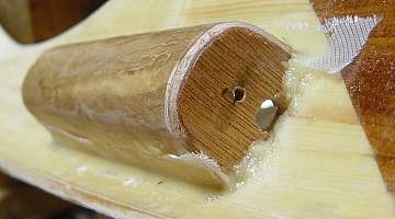 The ends of the slider recess were filled in with marine ply, also drilled
with holes to take the stainless steel bar and the control tube. A hole was
cut in the deck (after glassing both sides) slightly smaller than the inside
of the assembled recess. This was sanded to remove all sharp corners and
epoxy sealed. The recess was then glued to the inside of the deck with
thickened epoxy made into a fillet, which was then covered with glass tape.
After a certain amount of sanding off projecting bits of glass fibre and a
further epoxy fill coat (the control would be quite near my knee inside the
boat, so I wanted a good finish), the remaining assembly would wait until
after the deck had been fixed to the hull (and indeed, until after the maiden
voyage).
The ends of the slider recess were filled in with marine ply, also drilled
with holes to take the stainless steel bar and the control tube. A hole was
cut in the deck (after glassing both sides) slightly smaller than the inside
of the assembled recess. This was sanded to remove all sharp corners and
epoxy sealed. The recess was then glued to the inside of the deck with
thickened epoxy made into a fillet, which was then covered with glass tape.
After a certain amount of sanding off projecting bits of glass fibre and a
further epoxy fill coat (the control would be quite near my knee inside the
boat, so I wanted a good finish), the remaining assembly would wait until
after the deck had been fixed to the hull (and indeed, until after the maiden
voyage).
After the kayak was basically seaworthy, with hull and deck assembled,
cockpit complete and bulkheads and hatches installed, the final job was to
install the control tube and slider control, then cut open the outside of the
skeg slot and fit the skeg itself, which had meanwhile been attached to a
 length of stiff 4mm stainless steel wire obtained from my local boat
chandlers. I emphasise "stiff" here. There are two grades of s/s wire
used for rigging - one is a right-handed laid bundle of cables which
are themselves left-handed laid bundles of single strands. This is
very flexible so it can pass round pulleys and the like and not what
is needed for a skeg control which must "push" without kinking. The
other grade is a left-laid bundle of seven thicker strands and is
intended for standing wires. This does the job nicely.
length of stiff 4mm stainless steel wire obtained from my local boat
chandlers. I emphasise "stiff" here. There are two grades of s/s wire
used for rigging - one is a right-handed laid bundle of cables which
are themselves left-handed laid bundles of single strands. This is
very flexible so it can pass round pulleys and the like and not what
is needed for a skeg control which must "push" without kinking. The
other grade is a left-laid bundle of seven thicker strands and is
intended for standing wires. This does the job nicely.
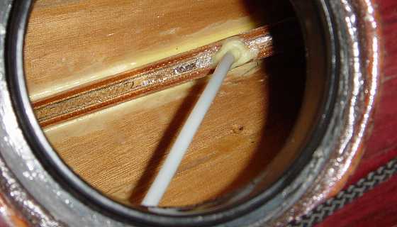
The control tube itself is a standard VCP nylon skeg control tube
obtained from my local sea kayak shop. First I had to drill out a suitable
sized hole in the top of the skeg box - there was a gap in the filler strip
for this, so all I actually had to do was cut out a small amount of the glass
tape. Getting at the skeg box was easy, since I had built in a small Kajak
Sport hatch far aft above the skeg box to provide access to this part of
the cargo space - this makes loading and unloading the kayak through the
aft bulkhead hatch a lot easier and avoids losing small items permanently behind
the skeg box ! Drilling a hole in the aft bulkhead was a little more awkward,
since I wanted the hole as close as possible to the hull, but didn't want to
accidentally damage the glassing on the inside of the hull. The tube was then
fed through this hole, along the inside of the sheer, and down into the skeg
box, held in place along the inside of the hull by a few blobs of holt-melt.
The tube was carefully cut to length and the other end inserted into the hole in the slider recess. At this point, the stainless steel guide rod was also inserted into the end of the recess, threaded onto the slider knob, and passed through the other end of the recess, where a second piece of tube was also added, to allow room for the end of the control wire to move. The rod and both pieces of tube were then fixed in place with thickened epoxy, being careful to seal all the drilled holes and the end of the short tube. I had also epoxied over the end of the control wire to be sure that it would neither fray in use, nor scratch the inside of the tube as it was fed through. The end of the wire was fed into the skeg box, carefully inserted into the tube and pushed until it popped out in the slider recess. It was then fed through the cable clamp in the slider knob, and fed into the other piece of tube. At the appropriate point as the amount of spare cable at the skeg end disappeared, the skeg blade was hooked over its pivot so that when the cable was completely absorbed into the boat, the skeg was in the retracted position. The position of the slider knob was adjusted and the cable clamp tightened. The position of the slider knob was chosen so that when pushed as far aft as the recess allows, the top edge of the skeg is still just within the box, so that the skeg is not too vulnerable to breakage if it is caught a sideways blow on a rock.
Problems - well, there were bound to be one or two. Firstly, the slider knob is just too tight a fit on the thin stainless steel rod which guides it along the slider recess. This makes it a bit prone to jamming, requiring a bit more care to operate than ideal. Given how the thing was put together, fixing this is difficult, but I have lived with it for two seasons and reckon I can live with it permanently, or at least until the control has to be dismantled for some other maintenance job...
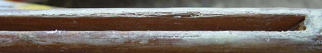 Secondly, the narrowness of the skeg box was continued right to the hull of
the boat, and this made it extremely prone to getting jammed by sand on beach
launches. I tended to test the skeg as soon as I had got through any surf,
but this then meant a surf landing and another launch from sand to fix it. In
the course of unjamming the skeg several times, using a borrowed knife, I
damaged the edge of the skeg box. The rather thin edges also took damage from
my rock-hopping games when the skeg was up, to the point where bare wood was
exposed. Obviously this needed urgent repair. I sanded the edges down to a
much more rounded outline with a lower profile than the rest of the keel. I
also sanded out the inside of the skeg box near the keel, so that the
Secondly, the narrowness of the skeg box was continued right to the hull of
the boat, and this made it extremely prone to getting jammed by sand on beach
launches. I tended to test the skeg as soon as I had got through any surf,
but this then meant a surf landing and another launch from sand to fix it. In
the course of unjamming the skeg several times, using a borrowed knife, I
damaged the edge of the skeg box. The rather thin edges also took damage from
my rock-hopping games when the skeg was up, to the point where bare wood was
exposed. Obviously this needed urgent repair. I sanded the edges down to a
much more rounded outline with a lower profile than the rest of the keel. I
also sanded out the inside of the skeg box near the keel, so that the
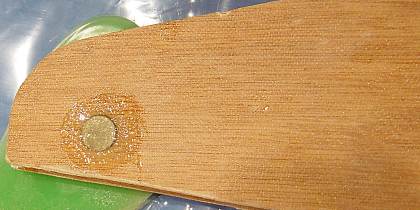
 internal shape was somewhat flared. I then added glass tape to both sides of
the slot, standing proud above the wooden edge, and filled the angle between
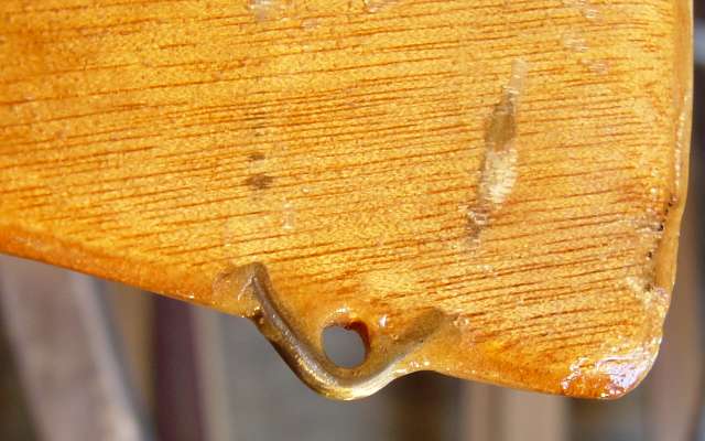
the wood and the edge of the glass tape with thickened epoxy. I also drilled
out two holes into the lower edge of the skeg itself, and inserted a bent
piece of stainless steel rod to form a small loop into which can be inserted
a piece of wire or similar to get a grip on the skeg and pull it down if
jammed. As it happens, the changes to the shape of the skeg slot have meant
that it has not jammed since making these repairs.
internal shape was somewhat flared. I then added glass tape to both sides of
the slot, standing proud above the wooden edge, and filled the angle between
the wood and the edge of the glass tape with thickened epoxy. I also drilled
out two holes into the lower edge of the skeg itself, and inserted a bent
piece of stainless steel rod to form a small loop into which can be inserted
a piece of wire or similar to get a grip on the skeg and pull it down if
jammed. As it happens, the changes to the shape of the skeg slot have meant
that it has not jammed since making these repairs.
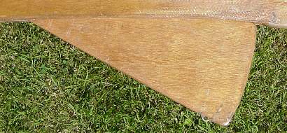
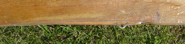 With the skeg retracted, the keel profile is not now quite so smooth, but
the skeg jams much less readily, can be unjammed easily, and there is
still no great open slot to cause turbulence and drag, so this is basically
the shape I would aim for in building another skeg system.
With the skeg retracted, the keel profile is not now quite so smooth, but
the skeg jams much less readily, can be unjammed easily, and there is
still no great open slot to cause turbulence and drag, so this is basically
the shape I would aim for in building another skeg system.